Troubleshooting Kwikee Steps / Basic Summary of Operation
There are three different methods of operating a Kwikee electric step:
1) The first method utilizes a self centering rocker switch that allows the step to be extended or retracted by pushing the appropriate side of the rocker switch. There is no control unit on steps using this method of operation and these are covered in a different manual #859.
2) Van steps are the only steps that use a door switch only operation. When the door is opened and it retracts when the door is closed. Instruction manuals are available for individual vans by make and model only.
3) The most popular operating method utilizes a door switch and a power switch. This is the method covered in this manual. The step will operate from the door switch which will extend the step when the door is opened and retract the step when the door is closed. The power switch allows the step to be locked in either the extended or retracted position. It will stay in this position regardless of whether the door is opened or closed and will remain locked until the power switch is turned on or the vehicle ignition is turned on. When the step is locked in the extended mode and the ignition is turned on, the ignition safety system will go into effect and the step will automatically retract. This is a safety feature designed so that the vehicle will not be driven with the step extended. On steps equipped with an orange control , there is a “last out” feature. This is a safety feature designed so that when door is opened the first time after the vehicle ignition is turned off, the step will extend, even if the power switch is turned off. On steps equipped with these control units, when the ignition is on, the step will always extend when the door is open and retract when it is closed.
Power is supplied to the system by the Red wire. The White wire turns the control on and off through the power switch. When the ignition is turned on, 12 VDC is supplied to the Yellow wire. This engages a relay that passes power into the system, bypassing the “off” power switch, and retracts the step automatically when the door is closed.
The control unit is essentially a current sensor as well as a switching device. When the motor assembly moves the step tread to its extended position, or stops moving because of an obstruction, such as a curb, or binding of a damaged or bent step frame, the motor draws a larger amount of current. The control unit “senses' the larger current draw and shuts off power to the motor.
WARNING: If the control unit shuts off power to the motor in the partially extended position, do not step on the partially extended tread or damage to the step fram and/or motor assembly may result.

OPERATING INSTRUCTIONS: Control Unit #9513
- Turn the step power switch “on”
- Close the door. The step should retract and lock in the up position.
- Open the door. The step should extend and lock in the down position.
- Turn the power switch off. The step should remain in the extended position. If equipped with an understep light, it should be off with the door closed.
- With the power switch off, the step extended, and the entrance door closed, turn on the vehicle ignition. The ignition safety system should retract the step.
- Turn the vehicle ignition off and open the door. The step should extend and lock in the out position (with the power switch off). This is the “last out” feature.
WARNING: If the door is opened and closed without allowing the step to extend and fully lock in the out position, the step will retract and lock in the up position. When the door is opened again under this condition, the step will not extend. In other words the “last out” feature is only functional one time after ignition is turned off without starting the cycle over by turning power switch on, then off.
When the vehicle ignition is on, the step will always activate with door movement regardless of power switch position.
DIFFERENCES: Control Unit #9514
The step may be locked in partially extended or retracted position by the “last out” feature if the entrance door is opened or closed while the step is in motion.
GENERAL SERVICE NOTES:
If the power to the step is disconnected and then reconnected, a current surge will more than likely cause a spark which is common. This does not necessarily indicate that the system is staying on.
If battery drain is suspected, observe the understep light(if equipped) while the step is extending. The power switch must be in the on position for the understep light to operate. When the step locks in the down position, the understep light should become noticeable brighter. If it does not, the control may not be shutting off. Turn the power switch off and unplug the four way plug between the control unit and the vehicle to prevent overheating the motor.
To further determine that the control unit is not shutting off, remove the two (2) screws from the connector on the motor leads between the motor and control unit. Remove the seal assembly. (See Figure 2) Place a voltmeter between the Red and Yellow motor leads then reconnect the four way plug. Turn the power switch on. If any voltage is read, the control unit is not shutting off and may be defective. When doing this test, switch the voltmeter leads back and forth between the Red and Yellow motor leads to be sure that no voltage reading is shown.
If the step does not work or operates erratically, such as extending part way and shutting off, the first item that should be checked is the vehicles battery. The voltage across the battery terminals should be at least 12.7 VDC with the engine running, or on shore power, and 12VDC when the coach is not on shore power or engine is not running. Monitor the battery voltage while extending or retracting the step. It should drop no lower that 11 VDC. When a battery is marginal the terminal voltage may fall as low as 8 VDC under load. and the control unit will shut off when the DC voltage drops below 9 VDC. When this happens, it will remember which function it was performing when voltage falls below 9 VDC and wait 2 to 5 seconds then will try to complete this function. If the required current drags the battery voltage below 9 VDC again, it will cycle off again for 2 to 5 seconds and continue this loop condition forever. This condition can also be caused by marginal or intermittent ground to the step.
The step may also operate erratically if it is connected directly to a converter and the converter output is not adequately filtered to supply a clean DC voltage. Normally, your house battery is the filter for a large number of low end Converter/chargers and a defective or disconnected battery can cause this.
If the control unit is hooked up electrically backwards, the step will not operate. If ground to the control unit is lost, either between the control unit and the step frame (green wire from control unit) or the step frame and the vehicle chassis (the braided ground cable) the step will not operate.
Check the step for physical damage. If the step has been struck by some kind of road hazard, the step mechanism may be bent, causing the step to bind. Check the tread, sliding rails, and extending arms for physical damage. Also check the pivot points for rust. (See the Lubrication and Maintenance Schedule).
If the power switch is on and the step will not extend when the door is opened and/or retract when the door is closed, but there is a clicking noise coming from the control unit (the engaging and disengaging of the relays in the control unit) the first item that should be checked is the motor. (See Motor Test Procedures ). The relays will engage and disengage (the clicking noise) when the door switch is cycled if the motor is malfunctioning.
TEST PROCEDURE-VEHICLE WIRING:

Unplug the four way plug between the control unit and the vehicle wiring to access the vehicle side of the 4 pin Connector.

MAIN POWER SOURCE TEST
Connect a voltmeter between the Red wire from the from the vehicle half of four way connector and the ground braid attached to the step frame. This reading should be around 12 VDC. If the voltage is low check for loose or corroded connections to the battery or low battery voltage. If the voltage is zero check the 25 or 30 Ampere fuse/circuit breaker. If you have 12 VDC proceed with next test.

POWER SWITCH TEST
Connect the voltmeter between the White wire and ground cable. The reading should be 12 VDC with the power switch on and Zero VDC with the power switch off. If the voltage reads Zero with the power switch on, check the inline fuse in the wire between the power switch and the power lead (Red Wire).

Check for 12VDC on both the input side and output side of the power switch (with it on). If you only have 12 VDC on one side, the power switch is bad.

DOOR SWITCH TEST
Connect the voltmeter between the Red wire from the vehicle side of the four way plug and the Brown wire in the same plug. The reading should be around 12 VDC when the door is open and Zero VDC when the door is closed. If the reading is Zero with the door open, check the ground connection from the door switch. An improper ground here can cause intermittent or erratic operation of the step. If the step will not retract after being extended or extends with the door closed, the Brown wire to the door switch may be touching a grounded surface inside of the wall or in the door jamb. With plunger door switches, insure that the switch is being depressed at least 2/3 of it's travel by the door. With magnetic door switched, insure that the magnet is positioned properly and that proper clearance is maintained between the magnet and the switch. If all above conditions are OK and you do not have proper voltage or erratic operation, the door switch may be bad.

IGNITION SAFETY SYSTEM TEST
Connect the voltmeter between the Yellow wire from the vehicle half of the 4 pin vehicle connector and and the ground cable. The reading should be around 12 VDC when the ignition is on and Zero VDC when the ignition is off. If the Yellow wire reads Zero VDC with the ignition on, check for a blown fuse or open wire to the vehicles ignition system. If the Yellow wire reads 12 VDC with the ignition off, it has been connected to a constant 12 VDC source.

MOTOR TEST
When checking the motor, remove the two screws from the connector on the motor leads between the motor and the control unit. Remove the seal assembly exposing the Red and Yellow wire connections. CAUTION: Make note of how the wires and assembly go together for later re-assembly. Temporarily connect a 10 Gage wire to the Red wire on the 4 pin vehicle connector leave other end free. Temporarily connect a second 10 Gage wire to the step ground cable and leave other end free.
TO EXTEND STEP: Connect the Ground jumper wire (fabricated above) to the YELLOW Motor lead. Momentarily touch the Power jumper wire from the Red wire (fabricated above) to the RED motor lead.
TO RETRACT STEP: Connect the Ground jumper wire (fabricated above) to the RED Motor lead. Momentarily touch the Power jumper wire from the Red wire (fabricated above) to the YELLOW motor lead.
If the motor does not move when power is applied in steps above but there is a small spark noticeable, there may be damage to the motor windings. Motor replacement is required.
MOTOR ASSEMBLY REMOVAL
The Motor Assembly Drawing is on another page and every reference in parenthesis below has been linked to it to in order to allow you to view the drawing easily. Simply click on any of the references then use your browsers back button to return to these instructions.
- Unplug the control unit from the vehicle (4 pin connector). Do not cut any wiring.
- Remove the (2) screws (Item #12) from the connector (Item # 18 and # 19) on the motor leads between the motor and the control unit. Remove the seal assembly. CAUTION: Note how this part is assembled in order to re-assemble it later.
- It is easier to remove the motor if the step treads are partially extended. If the motor will not function to do this, follow steps #4 and 5 below.
- Remove the hair pin (Item #6) from the clevis pin (Item #7).
- Remove the clevis pin (Item #7) from the cast block in the end of the linkage assembly (Item #8, #9, #10). Note which direction the clevis pin goes into the cast block. If the step is in its locked position the clevis pin may have to be pried or driven out of the block. If the step is in the locked position, loosening the motor assembly mounting bolts may allow the clevis pin to to be removed easier. The step treads should swing freely when the clevis pin is removed. If the tread does not move freely check for a bent step frame and for rusting at the pivot points.
MOTOR REMOVAL: The motor (Item #5) may be removed without removing the gear box or linkage assembly simply by removing the three (3) screws (Item #4) along with the bearing bracket (Item #2).
GEAR BOX REMOVAL: Unbolt the gear box mounting plate (Item #16) from the step frame.
- Remove the bearing (Item #3) and the linkage assembly (Item # 8, #9, or #10) from the gear case (Item # 11) along with the adapter gear (Item #1) and shaft (Item #17)
- Turn the gear box assembly over and remove the four (4) 1-1/4” long #10 self tapping screws (Item #13) from the gear case. Lift off the mounting plate (Item #16).
- Remove the bearing (Item #3). Lift off the gear case cover (Item # 15) and lift out the gear (Item #14). Note which side of the gear goes up.
LUBRICATION AND MAINTENANCE SCHEDULE
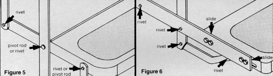
Clean all mud, salt, and road grime from the step before lubricating. Lubricate all moving parts ( bearings, pivot points, slides,clevis pin and drive linkage ball every 30 days with a good quality moisture and heat resistant penetrating grease. Kwik-lube Spray Grease is available for this purpose from Kwikee. Refer to figures below for lubrication instructions:
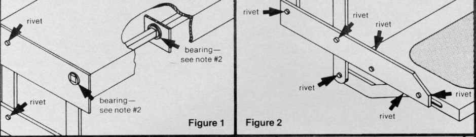
NOTE 2: Square Shaft Bearing - lubricate around outside and under head of bearing.
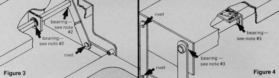
NOTE 3: 1“ OD Tube Bearing- lubricate around drive tube and between head of bearing and drive leg.