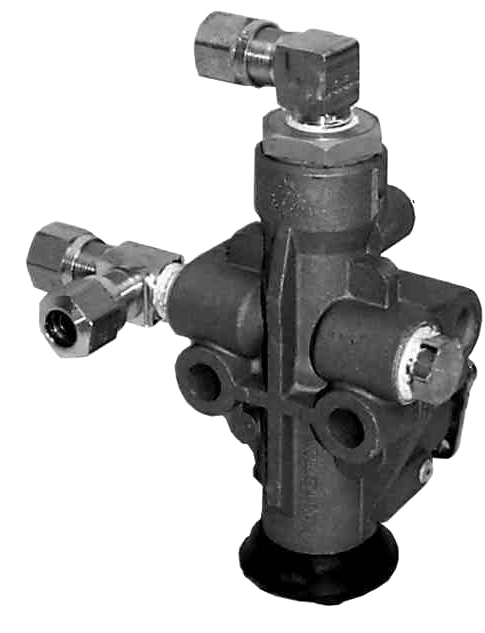

On coaches equipped with mechanical ride height valves, the typical setup is one valve on the front axle and two on the rear axle. The Valve is mounted to the frame and has a small bar connected to the suspension. When the suspension moves up and down the ride height valve's function is to add or dump air from the air bags such that proper ride height is maintained.
The single (1) front ride height valve controls coach “travel mode” leveling from front to back. The two (2) rear ride height valves control “travel mode” leveling from side to side. Rears are more important than front. The valve control rotates between add & dump, with center position being closed to keep air in air bags.
As the coach moves down the road the valves are continually adding or exhausting air from the air bags to maintain the ride height. The valves are designed to auto compensate for road variation, weight transfer and loads. They also have a dead band of about 3 degrees to compensate for “road jitter” as the suspension is moving over small bumps.
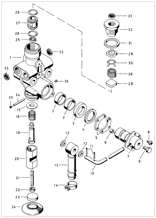
The pictures shown are a Wabco 4640024430 found on the front/rear axles of certain year coaches.
Ride Height Adjustment
The air bags have a quarter inch plate on the top and bottom of each bag. Sort of like a Oreo cookie with the bag being the filling and the plates being the cookie on the top and bottom of the filling.
Place your motor home on as level a slab as you can.
To measure the ride height one must choose one of two measurements.
- Measure from the top of the top plate to the bottom of the bottom plate, which should be 8.5 inches
-OR-
- Measure from the top of the bottom plate (where the bag sits on the plate) to the bottom of the top plate (where the plate sits on the bag), which should be 8 inches. This is the distance occupied by the air bag only.
Adjust the two rear height adjustments first. This should give them the correct height and the side to side measurement should be the same. Then adjust the single ride height for the front. On Foretravel 8-bags, you measure ride height on the bags TOWARD THE CENTER OF THE COACH , meaning the bags in front of rear drive tires and behind the steer tires.
Here is a good overview of the general proceedure
How Foretravel did air leveling before HWH.
Each of the three ride height valves (mentioned above) is mounted on a small pivot plate that rotate the whole ride height valve. Connected to the plate is a large sheathed cable (like the kind you see on boat steering) that rotates the entire ride height valve. When this is done it “tricks” the valve into thinking it needs to add or subtract air from the air springs.
The cables lead to 3 mechanical levers on the floor between the drivers seat and wall: Left for left rear. Middle for front axle. Right for right rear.Example: Push the middle lever forward = front drops down proportionally.
The brain of the system is between your ears: read the bubble, move the lever. Once the coach is level, it will stay that way as long as there is system air.
The levers have a center detent (with microswitches) to illuminate the dash “air level” light. Light goes out = travel position.
Exhaust Covers
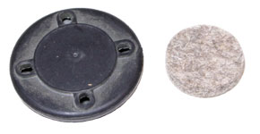
The OEM rubber covers for the ride height valves, deteriorate and fall off over time. Their purpose is to prevent dirt and contamination from entering the breather holes on the valves. They also provide some level of “muffler” to the outlet air. New covers are available for replacement, look for
- Haldex P/N RN10JE - Exhaust Cover Kit
When these fall off (and they will), be aware that mud daubers may choose to make a nest in them. They may get fowled closed or open at that point. You can easily clean the inside of the valve out with a toothpick and gently tap on the outside of the valve to get any debris out, then covered the hole with a breathable cloth until you get replacement covers.
Emergency leveling valve override procedure
If you find you have a leaking Ride Height Valve, you can use the following emergency procedure. Another Emergency Procedure If Your Ride Height Valve Fails
In order to get the coach back to ride height position it may be necessary to follow these steps.
Active Air Leveling System
- Manually raise low side of coach if rear control valve is bad or front of coach if front valve is bad.
- Once coach has been raised to travel height locate Active Air panel on dash.
- Press Stop button on Active Air panel and Coach is ready for travel.
- If all electronics have shut down then you can inflate air bags with Schrader valves located in storage bay to the travel position. Once ride height is achieved then you are set for travel.
HWH 2000 series leveling sys.
- Manually raise low corner of coach (attempting to locate center of air bag travel)
- Locate HWH control boxes in storage bays (frt. & rear air boards)
- Once boards have been located we will need to identify the brown 12 pin plug on front air board (if control valve is bad on the front)
- If coach is leaning to the left or right on the rear locate rear control board identify the 12 pin brown (in some cases may be black)
- Disconnect plug for the corresponding control box to valve that is failing
HWH 680 series leveling sys.
- Manually raise low side of coach if rear control valve is bad or front of coach if front valve is bad
- Locate HWH control box remove cover
- There is a series of circuit boards located inside of box (top and bottom boards) you will need to locate the 7.5 amp travel fuse and remove. (lower board)
- The coach will now hold to the level position you manually set
HWH 600 series leveling sys.
- Follow same procedures as on 680 series above.
- The only difference is the control box layout, there is only a single row of fuses locate the 7.5 amp fuse and remove.