An Introduction to Antilock Braking (ABS)
Antilock braking systems (ABSs) are electronic systems that monitor and control wheel slip during vehicle braking. ABSs can improve vehicle control during braking, and reduce stopping distances on slippery (split or low coefficient of friction) road surfaces by limiting wheel slip and minimizing lockup. Rolling wheels have much more traction than locked wheels. Reducing wheel slip improves vehicle stability and control during braking, since stability increases as wheel slip decreases.
ABS can be applied to nearly all types of vehicles and can be successfully integrated into hydraulic and air brake systems (including air over hydraulic).
How Do ABS Work?
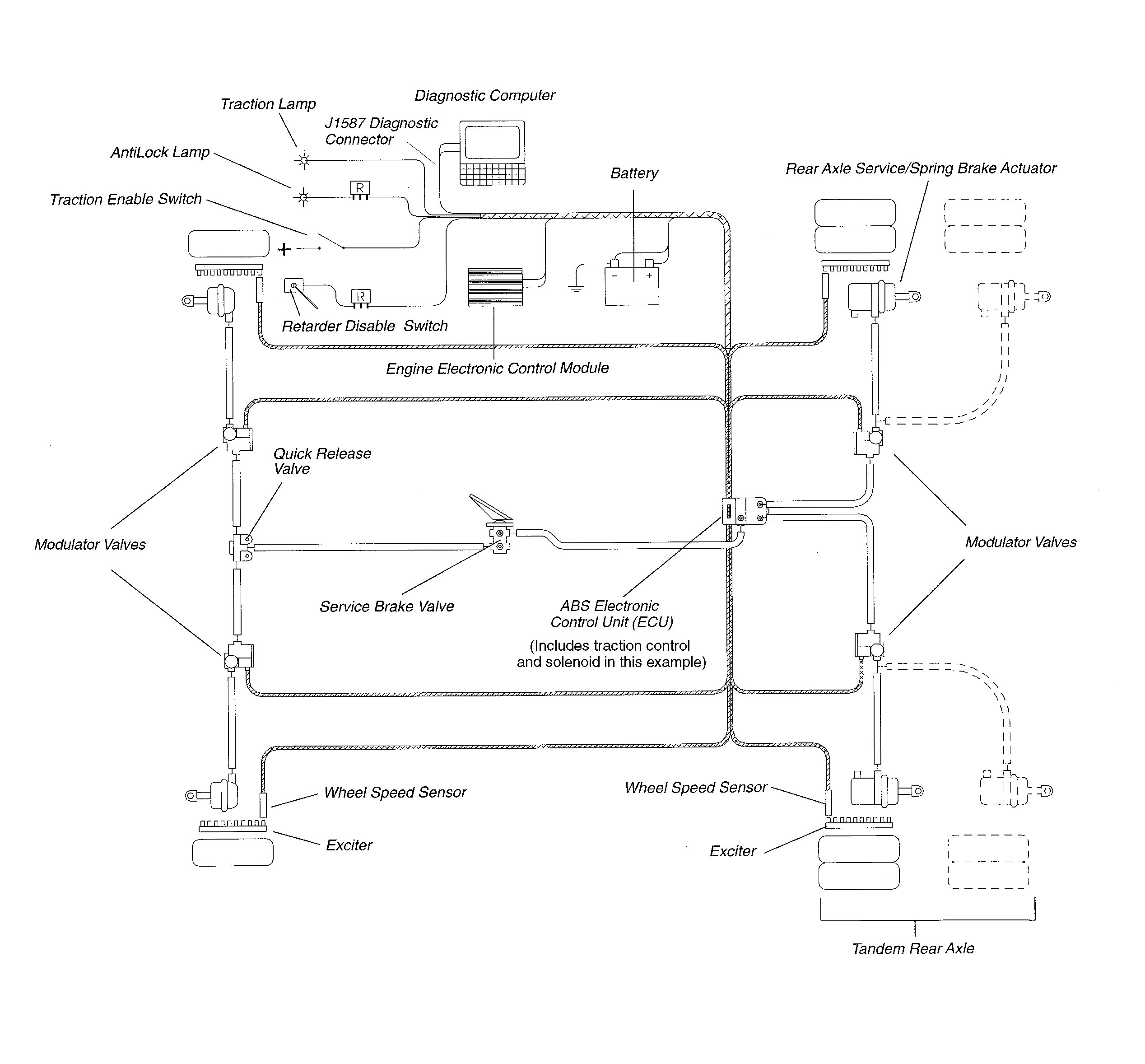
An ABS consists of several key components: electronic control unit (ECU), wheel speed sensors, modulator valves, and exciter rings.
Here’s how these components work together:
- Wheel speed sensors constantly monitor and send electrical pulses to the ECU at a rate proportional to the wheel speed.
- When the pulse rates indicate impending wheel lockup, the ECU signals the modulator valve(s) to reduce and/or hold the brake application pressure to the wheel(s) in question.
- The ECU then adjusts pressure, seeking one which gives maximum braking without risking wheel lockup.
- When the ECU acts to modulate the brake pressure, it will also (on most vehicles) turn off the retarder (if so equipped) until the risk of lockup is over.
- The ECU continually checks itself for proper operation. If it detects a malfunction/failure in the electrical/electronic system, it will shut down that part of the ABS affected by the problem —or the entire ABS— depending upon the system and the problem. When this happens, the ABS malfunction lamp lights.
An ABS adjusts brake pressure much faster and more accurately than can drivers. It’s faster because:
- Electronic controls are very fast and
- ABS modulator valves are physically closer to the brakes than is the driver’s foot brake valve.
It is more effective, too, because an ABS can tailor the brake pressure to each wheel or set of wheels to provide maximum braking/stability. Some vehicles also use a traction control system in conjunction with the ABS. Traction control helps the ABS improve vehicle traction by minimizing wheel slip on the drive axle during acceleration. If a wheel on the drive axle starts to slip, the traction control system automatically brakes the wheel slightly, transferring engine torque to the wheels with better traction. If all the drive wheels start to slip, the traction control system may also reduce engine power. Traction control systems are referred to by several different names, depending on the manufacturer. These include:
- Automatic Traction Control (ATC)
- Traction Control (TC)
- Automatic Slip Regulation/Anti-Spin Regulation (ASR)
How Should I Drive an ABS-equipped Vehicle?
It is the consensus of brake experts that drivers should brake an ABS-equipped vehicle just as they would brake a non-ABS equipped vehicle. The proper braking technique is to maintain a steady, modulated brake application. Modulated, in this case, means applying only the pressure required to achieve the desired deceleration. Do not slam on the brakes to make speed corrections or routine stops.
When operating on slippery surfaces, with or without an ABS, it is strongly recommended that drivers depress the clutch when braking. Engine braking itself can cause drive wheels to slip. Usually, any retarder will automatically be disabled when the ABS is in use.
Much of what is taught about hydraulic ABSs doesn’t apply to air ABSs. Thus, it’s important to remember the following:
- Brake as if no ABS is present, with a modulated application as described previously.
- Unless certain that the entire combination vehicle has a working ABS, don’t stomp on the brakes in a panic situation—one or more wheels could lock and cause the vehicle to jackknife. Even then, be careful because you can still jackknife or lose control if the vehicle is travelling too fast.
- Do not expect to feel the brake pedal pulsing or hear strange sounds when the ABS activates on air-braked vehicles. These vehicles do not transmit pulsing pressure to the driver’s foot and the driver probably will not hear the system cycling.
- Operate mixed combination vehicles (with and without an ABS) the same way one would operate totally non-ABS combination vehicles. Apply only the brake pressure needed to achieve the desired deceleration while ensuring vehicle stability. Monitor the combination vehicle behavior and back off the brake pedal, if possible, to keep the units under control.
ABS COMPONENT DESCRIPTIONS & OPERATION
This section describes the design and operation of ABS components. When you complete this section, you should understand the purpose and function of all major ABS parts including: the ECU, the modulator valve, the wheel speed sensor, ABS malfunction/indicator lamp, ABS diagnostic components, and traction control.
Modern antilock braking systems all feature the following major components:
- Electronic Control Unit (ECU)
- Wheel Speed Sensors (pickup and exciter)
- ABS Malfunction Indicator Lamps
- Diagnostics
Electronic Control Unit (ECU)
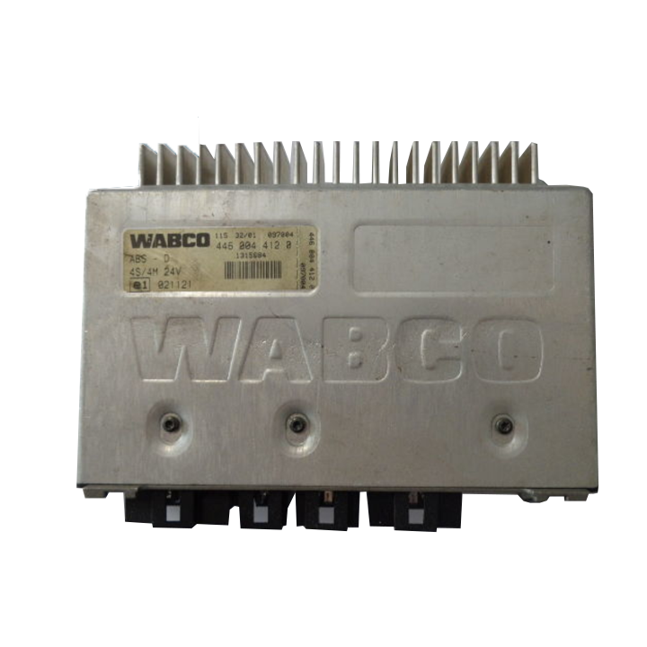
The ECU processes all ABS information and signal functions. It receives and interprets voltage pulses generated by the sensor pickup as the exciter teeth pass by, and uses this information to determine:
- Impending wheel lock-up and
- When/how to activate the ABS modulator valves.
The ECU connects to the following ABS components: wheel speed sensors, ABS modulator valves, power source, ground, warning lamps, blink code switch, J1587* diagnostic connector,and retarder control device (usually by relay or the J1922/J1939 datalink.) The ECU also makes self-diagnostic checks during normal operation.
During braking, the ECU uses voltage pulses from each wheel speed sensor to determine wheel speed changes. If the ECU determines that the pulse rate of the sensed wheels indicates imminent lock-up, it cycles the ABS modulator valves to modify brake air pressure as needed to provide the best braking possible.
The ECU sends signals to the ABS malfunction indicator lamp or blink code lamp to communicate ABS faults. It also sends signals to the retarder control to disengage the retarder when the ABS is working. When the ABS stops modulating the brake pressure, the ECU permits retarder use once again.
Modulator Valves
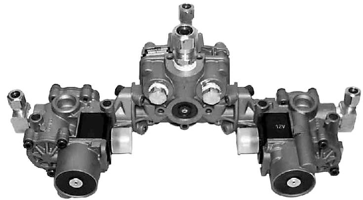
ABS Modulator Valves regulate the air pressure to the brakes during ABS action. When not receiving commands from the ECU, the modulator valve allows air to flow freely and has no effect on the brake pressure. The ECU commands the modulator valve to either:
- Change the air pressure to the brake chamber, or
- Hold the existing pressure.
However, it cannot automatically apply the brakes, or increase the brake application pressure above the level applied by the driver. The modulator valve typically contains two solenoids. The modulator valve and relay valve may be incorporated into a single unit. The modulator valve may also be separate, inserted into the service line to the brake chamber(s) after any relay valve, located as close as practicable to the chamber(s) itself. When the modulator valve is separate, it has to control more air flow and, therefore, includes two larger diaphragm valves which are controlled by the solenoids. It usually has three ports: the supply port, the delivery port and the exhaust port.
- The supply port receives air from a quick release or relay valve.
- The delivery port sends air to the brake chambers.
- The exhaust port vents air from the brake chamber(s).
Typically, when an ECU controlling a separate modulator valve detects impending wheel lockup, it activates the solenoids to close the supply port and open the exhaust port. When enough air is vented to prevent wheel lockup, the exhaust valve will close and the ECU will—depending on the situation—either:
- Keep the supply port closed to maintain existing pressure, or
- Open the supply port to allow brake application pressure to increase and repeat the cycle.
Wheel Speed Sensors
The wheel speed sensor has two main components: the exciter and the pickup. Other components include associated wiring and mounting equipment.
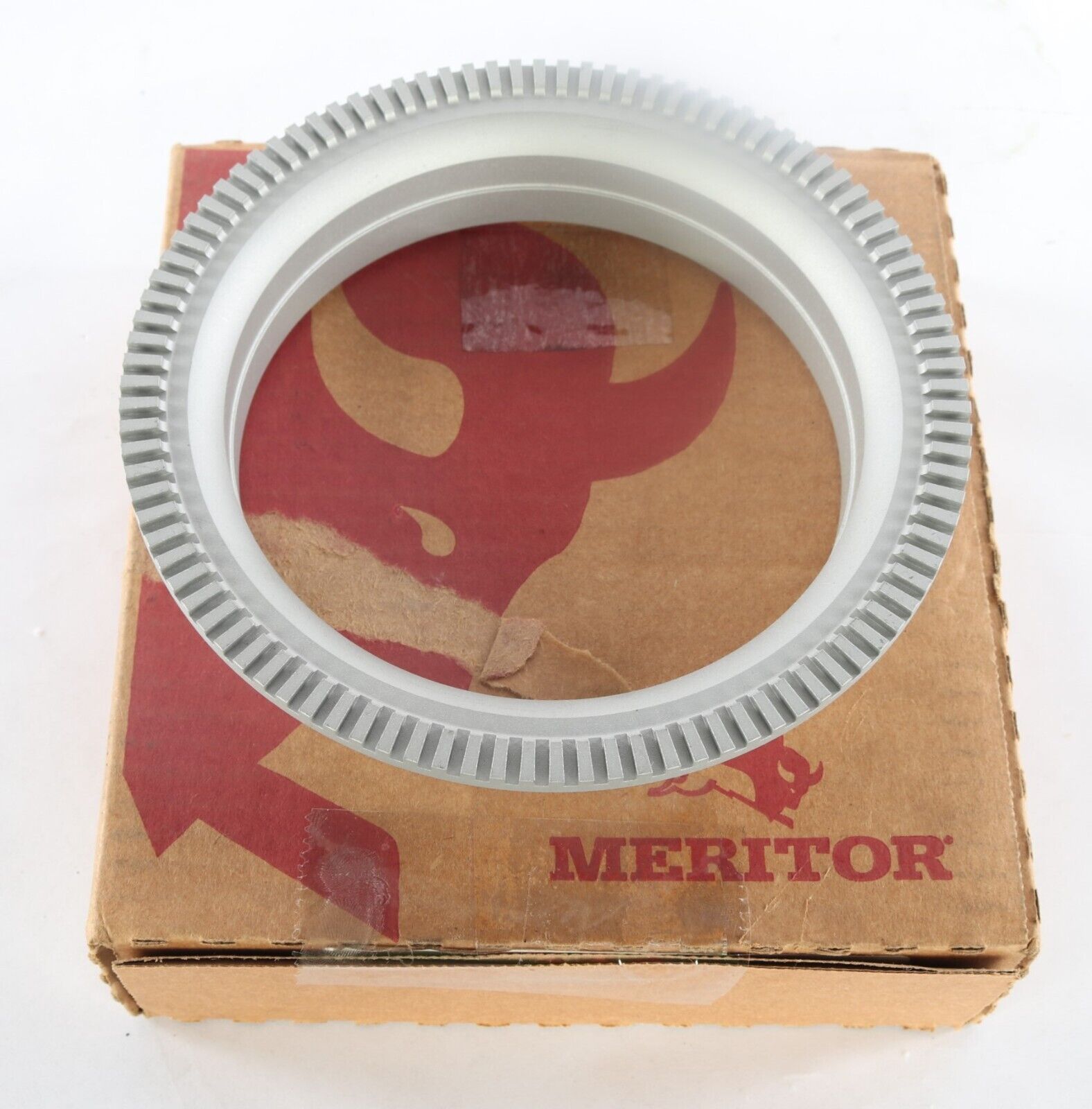
Exciter — The exciter is a ring with notched teeth. The most commonly used exciter has 100 evenly spaced teeth, but the number of teeth can vary depending on the system design. The component is known by several names: sensor ring, tooth wheel, tone ring, and exciter.
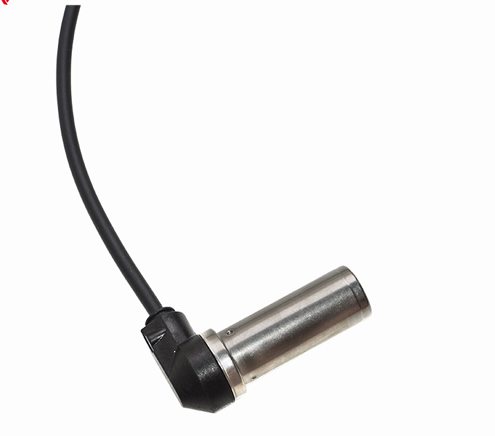
Pickup — The pickup is commonly called “the sensor.” It contains a wire coil/magnet assembly, which generates pulses of electricity as the teeth of the exciter pass in front of it. The ECU uses the pulses to determine wheel speeds and rates of acceleration/deceleration. The strength of these electrical pulses decreases rapidly with slight increases in the gap between the pickup and the exciter.
Wheel speed sensor location varies. It can be located anywhere on the axle to sense wheel speed. The sensor can be an assembly containing both the exciter and the pickup with a fixed gap. Or, the pickup and the exciter can be mounted separately on different parts of the axle assembly. The sensor pickup is a sealed unit and typically of elbow or straight design.
On most ABS air-braked vehicles, the pickup is located in the mounting flange on the wheel end. The exciter usually is either mounted on—or integrated with—the wheel hub. Since the output of the pickup decreases so rapidly with slight increases in exciter-pickup gap, it is imperative that the wheel end and sensor gap be maintained within the manufacturer’s specification.
When the wheels of only one tandem axle have wheel speed sensors, they are usually placed on the axle whose wheels are most likely to lock-up first during braking. On a tandem with a four-spring suspension, the sensors are generally on the lead axle. On a tandem with air suspension, the sensors are generally located on the trailing axle.
ABS configuration is defined by the arrangement and number of sensors and modulator valves used. The most common configurations for power units are:
- Four sensors/four modulators (4S/4M)
- Six sensors/four modulators (6S/4M), and
- Six sensors/six modulators (6S/6M)